
Power USB
ITEMS NEEDED
-
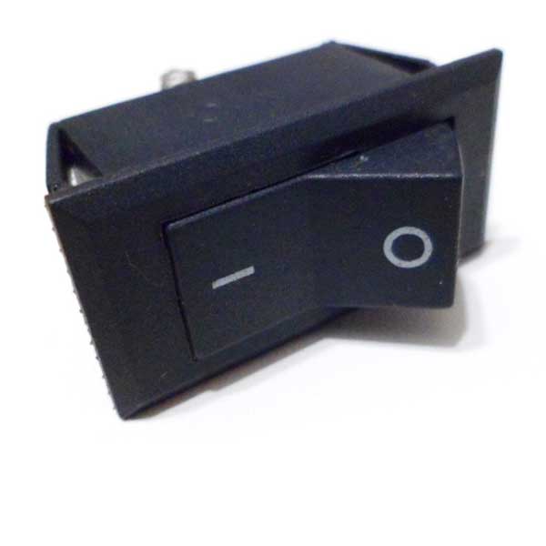
on/off switch
-
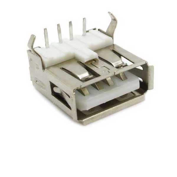
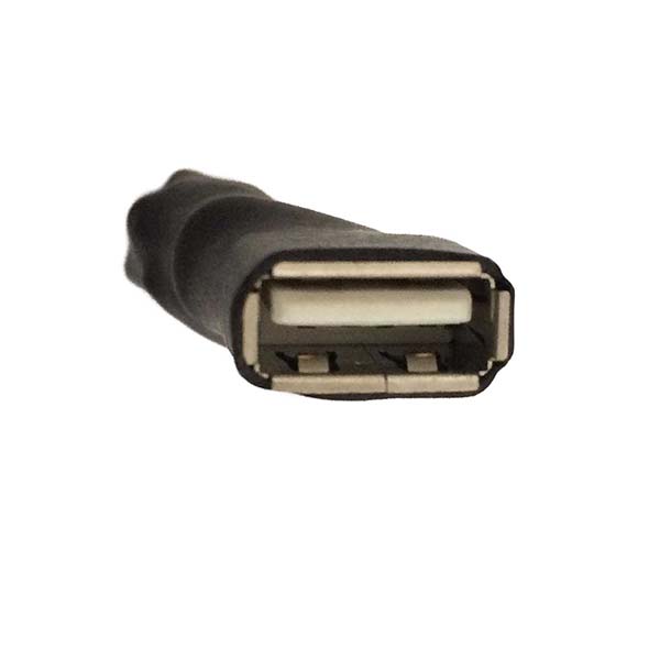
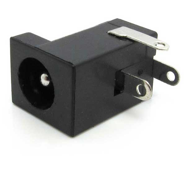
USB-A connector (Female)
-
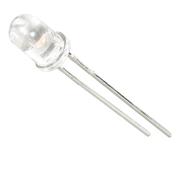
LED
-
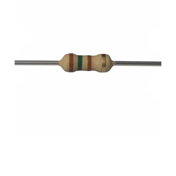
150R Resistor
-
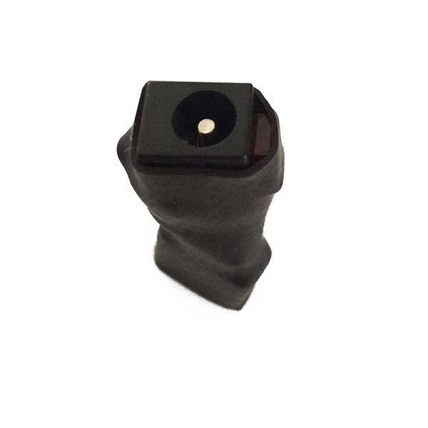
Female Connector
-

Heat Shrink Tubing
Electrical Tape
-
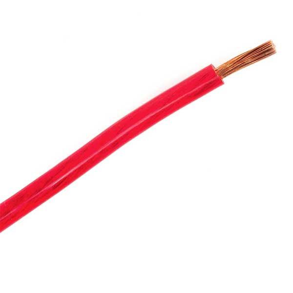
Electric Cable
Ethernet Cable
HOW TO ASSEMBLE
If you do not quite understand electronics, do not use the kit with 127V/240V wall USB chargers, because some of these chargers can supply a higher voltage, risking overheating the kit, even inducing electric shocks.
We recommend using the USB Energy module with portable USB chargers, like the ones used to charge Smartphones.
If it’s used on your computer’s USB port and it’s not correctly produced, it might damage the port and cause a huge loss.
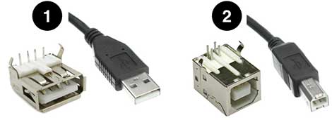
You may choose any USB pattern. In our tests, the Mini-USB and Micro-USB (used in modern Smartphones) has proven to be too fragile due to its really small pins. That’s why we recommend using connectors USB ‘A series’ (1), the pattern for computers and laptops; or USB ‘B series’ (2), usually used in printers.
We won’t use these lateral pins, they serve to secure the part in boards, which is not our case. You can fold them or just cut them off.
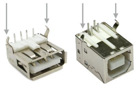
And fold the pins. This way all pins will be pointing to the inside, avoiding pointy tips when putting the heat-shrink tube.
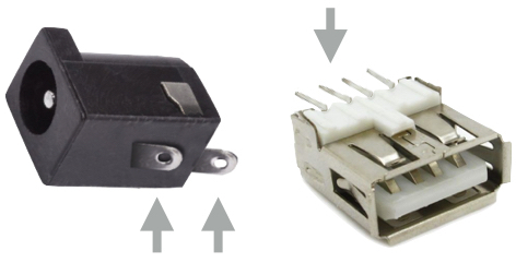
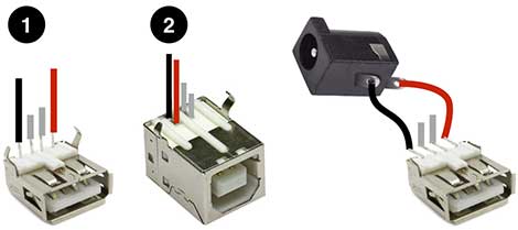
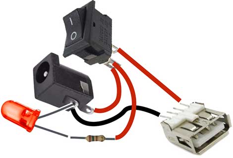
See in the image below where to put the positive cable (red) and the negative (black). The image shows female connectors USB ‘A’ (1) and USB ‘B’ (2). Ignore the grey cables, they’re in the image only to ease visualization of the existing pins.
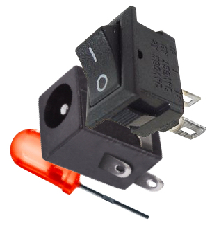
We recommend using a LED and an on/off switch. They’re optional, but we believe it facilitates a lot when using. You’ll need to put a resistor in the LED.
If you rather use the heat-shrink tube, we recommend leaving the connector, the switch and the LED side by side, with the female USB pointing the opposite direction, easing the finish.
watch the video
HOW TO TEST