
Connectors
The connector we use in the examples is the DC power, the same one used in cell chargers. But it is possible to use any other kind of connector.
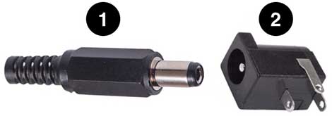
To accomplish its mission of taking power to all of the kit, the connectors have two shapes, the male and the female. In the kit we’ll use the male (1) to do the cables and the female (2) to the modules.
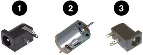
A module is made out of three parts: (1) the connector that receives the power; (2) the parts that execute the module function (in this image a motor) and; (3) A second connector to put on a cable and take the power to the next module.
To take the power, we need two cables, one for the positive pole and the other one to the negative.
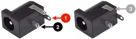
We’ll use the pin in the back of the connector (1) to plug the positive pole. And the pin right in the middle of the connector (2) we’ll use to plug the negative pole.
The lateral pin on the side of the connector (3) we will not use. If you rather, you can even cut off the lateral pin, this way it will be easier to solder and understand the diagrams. But do it only in one pair, solder, test, assemble a module, test. This way, if you did anything wrong you won’t ruin all the connectors.
We recommend soldering a connector right into the other (see the soldering videos), so it would be small enough to do an easy finish with the heat-shrink tube or the electrical tape.
They don’t need to be too close. If one of the connectors gets too close from the other, it might hinder the soldering process if you need to solder a cable between them, because the soldering iron tip may not fit and touch the plastic.
Other connectors
You can use any connector that connects two or more cables. Our examples use DC power connector. We considered several aspects to choose the connector.
1Ease of use for children
2Ease of producing the kits
3Ease to find in scrap
4Costs, in case its bought on stores
We believe that the connector DC power (1) is the best in the first two topics, it’s easier to children’s use and it’s easier to assemble the kits.
However, the last two topics (ease of finding in scrap and cost) may vary widely depending on where in the world you leave, so, we point here to different options of cables.
If you’re going to reuse connectors from scrap, you must:
1Cut the cables
2Find which one you’ll use for negative and positive poles
3Join the cables and finish with insulating material (like electric tape)
Telephony and network connectors
RJ11 Connectors (2) used in telephony cables, RJ45 connectors (3) used in computer network cables and the JST connector (4) and its varieties, well used inside old computers and in toys to connect the rechargeable batteries.
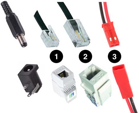
In the telephony and network cables (RJ11, RJ12 and RJ 45) use the central spaces to put the positive and negative pole’s cables.
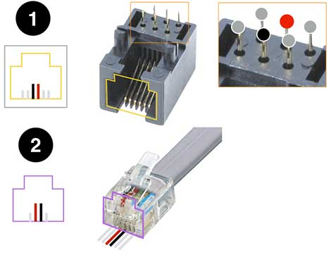
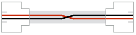
Since the positive and negative poles are side by side, a certain care is needed when building these cables. If you point the cable downwards, the positive pole will be on the right side, if you point it upwards, it will be on the left. So, when you’re assembling the cable, you’ll need to pay attention on this to get it done right.
When using a crimping pliers is very easy to place the cables. On YouTube there are many videos showing how to do it. There are also videos demonstrating ninja techniques of doing it without the special pliers.